![]()
A Lego Technic Suction Pump
![]()
![]()
A Lego Technic Suction Pump
![]()
![]()
![]()
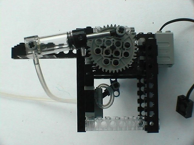
This model or just a mechanism is a suction pump built around modern pneumatic components. Apparently, there were old Lego pneumatic parts that could be used to build a suction pump. Some have modified a normal pump to do the same. This mechanism uses a pneumatic cylinder and a pneumatic switch to build a suction pump. This proves that new pneumatic parts do really suck:)
![]()
![]()
![]()
![]()
A crank converts rotary motion into reciprocating motion. In this model, the rotation of the motor is converted to and fro motion of the piston in a cylinder. It is also used to convert the motor rotation to to-and-fro motion of the lever on a pneumatic switch.
A straight part, in this case the cylinder, is attached to a wheel with a pin. The other end of the straight piece is fixed or slides along a fixed point.
The two main distances for a crank are the distance of the pin(A) from the centre of the wheel(B) and the distance of the fixed point(C) from the centre of the wheel. The two extreme positions of the straight part are when the pin is at D and E. The distance between these two points is the travel. It is twice the distance between A and B.
Given the travel and the minimum length of the straight part, the other details can be arrived at. In this model, we are using a cylinder. The cylinder has a minimum length of 6 SW(Stud widths) and a travel of about 3 SW. This would require the distance of A to B to be about 1.5 SW. Looking at possible attachment distances for some common parts, I picked a 40t gear. This gives slightly more travel than required on one side but seems to work without problems.
The motion of a crank is not uniform. Most of the to-and-fro motion happens in the parts marked in red and very little in the parts marked in blue. We will be using this interesting property in this model.
![]()
![]()
A picture of a pneumatic switch is shown below along with two block diagrams of it. The first diagram shows the lever in the up position. In this position, the B and C tubes are connected together and the A tube is open. The D tube shown in the diagram is not visible in the real switch. With the lever in the down position, the A and B tubes are connected together and the C tube is open.
 |
 |
 |
![]()
![]()
The suction pump brings together the concepts described above. The pneumatic cylinder and pneumatic switch are driven off the same axis but the cranks are 90° out of phase. This means that the motion of the cylinder piston occurs when the pneumatic switch hardly moves and vice versa. This can be achieved by having the points of attachment on the wheels 90° apart or, as in this case, the stationary points are 90° apart.
 |
 |
 |
 |
![]()
![]()
The parts were just thrown together as you can see from the big-chunk-o-plastic look. All parts are from the RIS 2.0 set. In addition, pneumatic parts from the UBS set were also used.
The parts required apart from the RIS set are the following.
![]()
![]()
 |
 |
 |
||
© 2007 Prashant Bhandary. Updated on
16 Feb 2007. Feedback to