 |
pic @ silicon junction |
How Cool is a Cree?
I was getting tired of my swimming pool lamp leaking and/or blowing up. I have been through a few replacements and the current status is - not working. So I wondered if a set of Cree XP-G LEDs could be used. I wanted the light to be as bright as the conventional halogen lamp, if not brighter. To do that, I wanted to pump as much current through the LED as possible.
Introduction
The Cree XP-G specs have the flux measurements taken at a current of 350mA. The max current is stated as 1.5A. So what is it that prevents the LED being driven by a higher current? It was not clear what was the limit for the LED. Is it the maximum current you can pump through it while still preventing it from heating up beyond the junction temperature of 150°C? Can I pump the maximum current of 1.5A now that I have 10,000 litres of water cooling the LED? I wanted to look at various designs to see how they perform and the maximum current I could use without heating up the LED too much. I wanted to vary the current, the heatsink design and cooling techniques and measure the effect on the junction temperature. Fortunately, inside each Cree LED, there is a thermometer.
Principle of Operation
The specs say the temperature coefficient of voltage is -2.1mV/°C. This can be used to measure the temperature of the junction. The measurement is best done with a low current through the LED. This removes the effect of the current on the junction voltage.
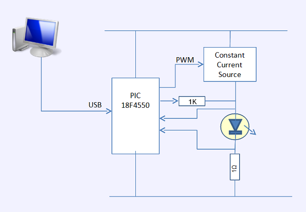
A PIC drives the circuit. The LED can be driven at different average current levels using a constant current source driven by a PWM signal. To measure the LED voltage using a low trickle current, a PIC output and a series resistor are used to drive the LED. The measured voltage can be used to calculate the junction temperature. When the PWM output is on, it also measures the current through the LED. The details are fed back to a PC host through the USB connection. The USB connection is also used to send commands to the PIC to adjust parameters like PWM duty cycle.
Circuit Design
A PIC 18F4550 based SBC, the Modtronix SBC44UC, is used to drive an XP-G LED. The LED requires a constant current source. Constant current drivers seem pretty elaborate and expensive. But if you are not using a bike light and wanting to squeeze the last watt out of a battery, a simpler, less efficient current source should be fine.
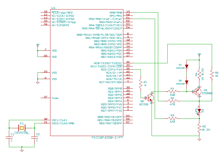
A simple constant current source built around a voltage reference using two diodes(D1 and D2) coupled with a resistor(R4) and an STD888 transistor(Q1) is driven by the PIC. The PIC can turn the current source on and off using a PWM signal. The current through the resistor is the difference between the voltage reference (1.2V) and the Vbe of the transistor (0.6V). For a resistor value of 1 ohm, this is 0.6A. A 1 ohm resistor is used to measure the current through the LED. The voltage across this resistor is fed to a PIC A/D input as is the voltage across the LED.
Construction
It is just an experiment so I took a 30cm x 7 cm x 12mm piece of MDF. I mounted the Modtronix SB44UC SBC, a breadboard and the Cree XP-G LED mounted on a star PCB on the MDF board.
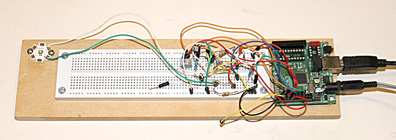
The USB cable goes to a PC and the DC power input comes from a bench power supply set to 9V. If you can spot the trimpot, it is fed into an A/D input and was used when checking the A/D code.
Now that I have made the transition to SMD components, I use them even when I am breadboarding. They may eventually go on a PCB and I might as well use the component I may end up using. I cut the normal breadboard wires in half and solder the wires to the component and use it on the breadboard.
Firmware
As with most of my projects, the firmware is driven by a periodic interrupt at a tick every 50us. The PWM cycle lasts 100 ticks. This will give a PWM frequency of 100Hz with a duty cycle varying from 1% to 100% in 1% steps.
The PIC sends a string to the host every 0.5 seconds. This string contains all measured values. Flags are reset once the string is sent out. The PIC will acquire the measured value at the first opportunity and set the flags. The host can send a command to set parameters, currently only the duty cycle.
- D n<CR>
-
Set duty cycle sent by the host to the PIC
n => Value between 0 and 100 for a duty cycle between 0 and 100% in 1% steps
Response is OK or ERR - R d I V<CR><LF>
-
Sent by the PIC to the host every 5 seconds
d => Current duty cycle value between 0 and 99
I => LED current raw value between 0 and fff
V => LED voltage raw value between 0 and fff
The code is in a single C program . I have left out the standard USB code which is based on the Microchip USB library and has some customisation specific to the SBC.
Software
A java program is used to set up a measurement session. It uses the command set to vary the duty cycle over time. It gets the received data and saves it in a CSV file. It does some simple pre-processing like gathering a certain number of samples and averaging them. It also plots a graph of the duty cycle and the LED temperature over time.
Results
The current source is configured to provide 600mA but the current sense resistor shows a drop of 1V or a current of 1A. The duty cycle was started off at 0 and then stepped up to 25%, 30%, 35%, 40% and 45% and similarly back down to 0%. A java program was used to set the duty cycle, convert the raw A/D reading to a temperature and plot it. The graph is shown below.
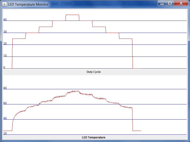
The Cree XP-G came mounted on a 20mm star PCB and it was just screwed on to an MDF board. At a duty cycle of 45% with an average current of 450mA, the temperature goes up to 78°C. This was confirmed by using an accurate thermometer viz. my finger and was measured at ouch! This is well below the junction temperature of 150°C.
The measured voltage varies quite a bit. The variation was about 5 counts which comes to roughly 10°. This seems to largely due to the measurement being taken in the middle of the LED being on. The firmware does shut the LED before measurement but the temperature does end up higher.
References
Datasheet for the Cree XP-G
The XP-G was sourced from Cutter Electronics
I use the Modtronix SBC44UC for most of my PIC projects.
A video blog on heat dissipation of an XP-G and another on using an XP-G in an existing product by Dave the Multimeter Hunter
Last updated on 10-July-2010
feedback
to  |