 |
pic @ silicon junction |
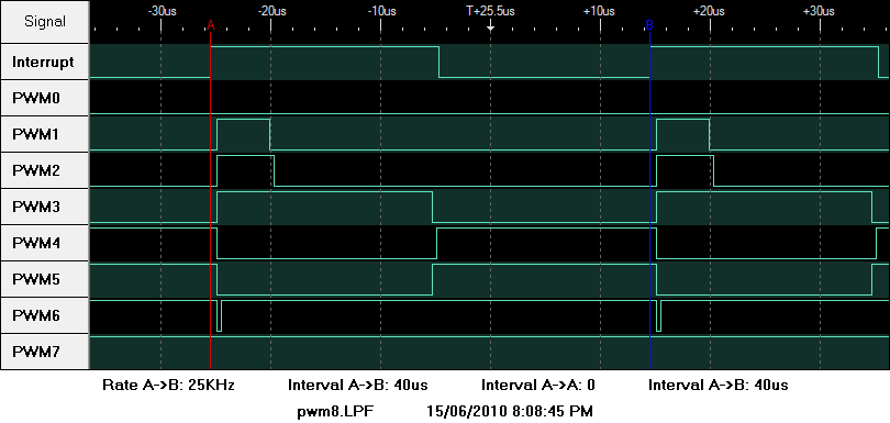
A 100 step 8 channel 25 KHz PWM circuit
Introduction
As part of building a multiple unit SMPS, I needed to drive four PWM channels. To keep the inductor size down, the frequency had to be tens of KHz. My current PWM circuit was a 20 step producing a frequency of just 1.25 KHz. The PIC 18F family has chips with one or two PWM channels but there are no 4 channel chips in small packages.
This circuit has the following features:
- 100 step resolution
- Operates at a PWM frequency of 25 KHz with a 20 MHz crystal.
- Up to 8 channels. All outputs must be on the same port and unused pins on that port can only be used as inputs or slow outputs.
- The ISR uses up a little over 50% of the processing time
The software can increase the PWM frequency to 60 KHz with a 48 MHz clock.
Circuit Design
The circuit is too simple to describe in detail. Just an SBC with the outputs connected to a logic analyser.
Firmware
As with most of my projects, the firmware is driven by a periodic interrupt at a tick - once every 40us. A buffer holds the bit pattern to be output on the port pins. Within the ISR, the code just reads from the buffer and outputs it on to the port.
The main routine sets up the buffer based on commands received from the host.
- Dchn dc<CR>
-
Set duty cycle for channel sent by the host to the PIC
chn => Value between 0 and 7 for channel
dc => Value between 0 and 100 for a duty cycle between 0 and 100% in 1% steps
Response is OK or ERR
The code is in a single C program with a simple include file with the I/O configuration. I have left out the standard USB code which is based on the Microchip USB library and has some customisation specific to the SBC.
Problems Encountered
Initially, the PWM waveforms were inconsistent. I changed from an XOR approach to just MOVF with no improvement. I used the MPSIM Logic Analyser and discovered the BSR. I set the BSR within the ISR and the problems went away. I don't know if it affects the main routine. I should use the MOVFF instruction, which does not use the BSR.
Last updated on 10-July-2010
feedback
to  |