 |
pic @ silicon junction |
Using PIC microcontrollers (2009)
I have returned to using PICs after a long break. The last time I used PICs was in 2002 and the last time I worked on a DCC implementation on a PIC was in 2000. Things had changed meanwhile - I had already progressed from the 16F84 to the 16F87X chips. I spent some time researching what had changed in the PIC landscape. Also, I was happy to spend a lot more to get my projects working as I was getting tired of projects remaining unfinished due to one problem or another exceeding my short attention span.
Transition from 16F to 18F
I moved from the 16F family to the 18F family. The 18F chips allow a faster clock (40 MHz instead of 20MHz). This will give much needed extra cycles during ISRs and this was a major bottleneck the last time around. I have often considered moving from ASM to C and the availability of a free C compiler for non-commercial use is an offer I could not refuse. The chips go beyond RS232 and support modern protocols like USB and ethernet. Serial ports are becoming rare and close to extinct on laptops. USB is the way to go with higher throughput speeds and almost unlimited expansion. Development of USB based projects is further simplified by free libraries from Microchip that simplify I/O routines on the chip. They also provide drivers for the PC allowing the USB port to look like a serial port to programs running on the PC. This made it easy to move my code from an RS232 based design to a USB design. The fact that I could not find drivers for my old USB to RS232 adapter was an additional incentive.
Another interesting development is the availability of an ethernet controller chip to build PIC projects with ethernet support. Newer PIC chips incorporate this ethernet controller providing a single chip solution for ethernet applications. While I haven't yet got a project to use this ability, it is worth exploring.
Using off-the-shelf SBCs
In order to avoid the usual delay in breadboarding a circuit followed by a PCB or sometimes straight to a PCB, I used off-the-shelf SBCs this time. I changed the design so that the micro controller and the drivers are on separate boards. This will allow me to use an SBC, change SBCs or design my own PCB without affecting the driver board. While looking for an SBC, I looked at the following criteria.
- Easily available and quick delivery to Australia
- Easy interface to the driver board with enough I/O lines and the right I/O pins available on connectors.
- Use easily available components allowing me to make my own PCB if needed
- Preferrably, any SMD components used have a non-SMD alternative, in case I need to build my own PCB. This may not always be possible.
The two SBC sources I ended up using were Modtronix and Olimex.
Modtronix have a a series of SBCs that support RS232, USB, Ethernet and CAN. Their numbering system is based on the number of pins on the PIC chip used e.g. the SBC44UC uses the 44 pin TQFP package. The letters forming the suffix is the important bit - it tells you the features available for the SBC e.g. UC indicates USB support, EC indicates Ethernet support and PC indicates CAN support. If the PIC is a TQFP package then it comes mounted on the board but PIC chips in DIP packages do not come mounted and you have to supply your own. All this is not obvious and took some time for me to figure out and I am still unsure if I've got it right.
Modtronix usually have the boards in stock and can ship it across in a couple of days. The boards come with the software modified from the original Microchip code to suit the Modtronix board. The documentation is thorough and can be downloaded from their website along with schematics. This allowed me to do an armchair evaluation. The boards have a large number of I/O lines available on headers. I used the SBC44UC USB board based on the 18F4550 in a TQFP package. The SBC with Ethernet support was not to my liking. It did not use a single chip solution. The Microhip ENC28J60 is a good companion chip for Ethernet support and it comes in a DIP package. However, the two chip solution in the SBC44EC (now superseded by the SBC65EC) does not use the Microchip ENC28J60 but an RTL8019AS. The web server uses a slightly different (and for my purposes, better) approach from the Microchip firmware.
Olimex have a series of SBCs with USB and Ethernet support. The USB SBCs come with large prototyping areas. The prototype board for USB has plenty of peripherals on board but very few I/O lines available. I found headers with most I/O lines on the Modtronix USB SBC more convenient. They have a very extensive range of SBCs with Ethernet support. Of these, the Micro Web Server particularly caught my eye. The size of the critter is amazing - the while thing is packaged inside a 25 pin D connector with the I/O lines available on the connector pins. There is plenty of I/O lines available and plenty of memory unlike most of the others in their product range. It uses the single chip solution. The coolness factor alone meant I had to get one of these without even having a project in mind for it.
Most Olimex boards are in stock at Dontronics and Don ships them across in a couple of days. The boards come with software modified from the Microchip code to run on the board. The documentation is extensive - I especially liked the comparison between boards with ethernet support. It saved me having to go through every datasheet.
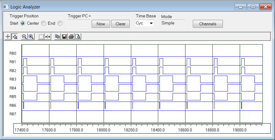
MPSIM and the Onscreen Logic Analyser
One of the first things I did was to download the latest MPLAB and run it. The new MPSIM has a logic analyser - the single biggest enhancement. This allows checking the program. I find this functionality so vital that in the past, I used a cumbersome procedure to get the trace file and display it as a timing diagram. I have been using this function extensively and found it to provide an big improvement in the development time. In its current form, it only traces I/O pins but with a few debug statements to output any register bit on an I/O line, any flag or variable can be displayed. I have used this to generate and debug timing diagrams. You can also save the screen image or output it as a text file.
Writing for the PIC in C
I am returning to C programming after a very long break. returning to c after a while. what are good coding practices for C and uc C? I am structuring the program files in a particular way. The main program has the main task and isr vectors. Each task is in its own file. It has three entries - the init() routine, the ISR service() routine and the cooperative multitask routine task(). The service() routine should be prefixed with the tmpdata related pragma. The main routine calls all the service() functions in the ISR, calls all the init() routines at the beginning and then calls all task() routines in a loop. good preso on interrupts on mc site.
Using the PICKit2
The PICKit2 (now superseded by the PICKit3) is a great programming and debugging tool. It is supported by MPLAB and runs off the USB port on a PC. It makes it easy to program a PIC onboard (useful for SMD parts) and allows debugging using breakpoints and single stepping within MPLAB with the ability to view register contents. It uses a 5 pin header and I have started including this in all my boards. The unit is quite inexpensive (AU$41 for the PICKit2 and $51 for the PICKit3).
Using the Intronix Logic Analyser
I have been thinking of getting a DSO for a while. I came close to buying the Rigol 1052E reviewed by the Dave, The Multimeter Hunter but did not like having just two channels even if they were full analog ones. I opted for a USB based 34 channel Logic Analyser from Intronix for a little over AU$400. Besides the usual logic analyser functions, it also allows decoding RS232 which I found really handy debugging some of my projects. I usually output debug signals on spare PIC outputs and I have started using this to trigger the logic analyser. I have found this approach very useful a number of times.
Using the Rigol 1052E DSO
OK, so I finally bought the Rigol. This is handy for checking out analog signals. It is a big improvement over my old Digitor oscilloscope. Among its many features is the ability to save a displayed waveform to a USB memory stick.
Designing PCBs
OK, so this is not to do with PICs but as part of the wave of new technology sweeping through my workbench, I am not rolling my own any more. I used to layout single sided PCBs the hard way in a general purpose CAD program (TurboCAD). With my vision not being as good as it used to be, it is getting difficult to drill holes in PCBs. It is also getting easier to get PCBs made.
I started using Kicad , which is a open source schematic editor and board layout software. It also has a great web based application that can be used to auto-route the board. One of the great features of Kicad is all its file formats are text based. I find this convenient to check details or make small fixes. For example, I have programs to scan the board file and generate a report on the components used, no. of pins, pitch(for two pin devices), the pad and hole sizes. I load this into a spreadsheet and cross-check this against the actual component lead sizes. I also check if the pads are big enough for the hole size. If they are incorrect, I simply change it in the text file before doing an auto-route. I am beginning to build a few useful utilities around this package to help me with the schematic and layout work. There are a few tutorials on how to use the package. There are no size or pin limitations. It outputs Gerber files. The file format is partly documented. As the source is available, some of the file format issues can be checked out by looking at the source.
I am using PCBCart to get my PCBs made. I have used them once so far. It cost about AU$125 to get 5 nos. of a 56 x 72 mm double sided PCB with a black solder mask on both sides, a legend silk screen on the component size and including shipping. The quality is pretty good and it takes a couple of weeks to deliver. The Gerbers from Kicad worked fine.
Using SMT
As one of the components in one of my projects came only in an SMD version, I decided to take the plunge and do the Wallex project using SMD parts. As an additional benefit, I was able to keep the size very small. I haven't tried actually assembling it yet but I am looking forward to it. With dodgy eyesight and unsteady hands, I expect it to be a challenge.
Sourcing Components
Sourcing components is always a pain. I first tried ordering stuff from Futurlec. They had a limited selection but great prices. When I placed the order, nothing happened. Emails and faxes to them elicited no response. I gave up and found alternate sources and the parts finally arrived six months later! I would not be ordering from them ever again. There are the popular ones like Mouser and Digikey but the freight to Australia can be pricey, especialy if it is a small order. I started using the local suppliers Farnell and RS Electronics and was pleasantly surprised. The old days when you try to get those big paper catalogues to order from are gone. It is all on the web with fairly easy ways of searching the parts database. Datasheet are also easily available. They have a very comprehensive product line. Freight within Australia is free allowing you to place an order for that single 1 cent resistor you needed. The prices looked a lot more reasonable compared to when I last looked at them. If they have it in stock, you get it within a day. I am basing all my component choices based on availability at these two sources. Of the two, I prefer Farnell as they seem to have almost everything and at a cheaper price though RS is a better site for SMD crystals. I have had orders placed in the middle of the night being delivered the next day at 10:30AM!
Disclaimer: I have no affiliation with any of the suppliers mentioned above.
Last updated on 10-July-2010
feedback
to  |