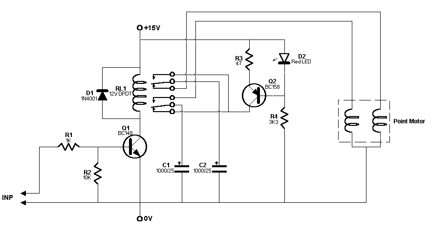
Turnout Interface
Circuit Diagram

Circuit Diagram in Postscript(26K)
Circuit Description
The signal from the I/O Extender drives transistor Q1 to activate
the relay. This causes the capacitor C1 to discharge through one
of the coils of the turnout motor and moving the turnout frog in
one direction. The capacitor C2 is then charged by the constant
current source made up of Q2, D2, R3 and R4. When the signal from
the I/O Extender goes low, the relay is deactivated. This discharges
C2 and charges up C1.
The constant current source reduces the cycle time as explained in
the turnout controller page.


Updated on 23 Nov 95. Feedback to 


