 |
dcc @ silicon junction |
Overview
I have always been interested in electronics, especially micro controllers. I also enjoy programming - for work as well as a hobby. Once I got interested in model railroads, it was inevitable that the three come together and I start controlling a DCC based layout using a computer.
My interest is primarily on the electrical side and the layout itself is secondary. As far as possible, I try to build my own DCC equipment. The mobile decoder is an exception. The required size is too small (I model in N scale) and there are other components to build first. Mobile decoders are also becoming cheap. I also don't look forward to install decoders into locos. These days, I am a complete wuss and buy locos with decoders pre-installed.
Unlike most model railroaders, building the DCC system is an end rather than the means. Most components I design and build are just for the fun of it rather than to save on cost. So, generally, my solutions are not always low cost.
Design Philosophy
The philosophy of my setup is to depend on a PC for any complexity required by the system and for an easy to use user interface. The command station interfacing to the layout is kept relatively simple. Moving the manual controls from a physical implementation like a throttle to a few screen elements makes building the system a lot easier and lets me play around with the PC based programming.
The design is strongly influenced by the tools I am comfortable with. With micro controllers, I started on the venerable PIC 16C84 and I have continued with PIC microcontrollers. Last time around I moved to the 16F876 and now it is the 18F family. I started off with PIC assembly code but have now moved to C thanks to the availability of the free version of the Microchip C18 compiler. The programming language of choice on the PC is java. I am not a great fan of swing, preferring a web based HTML and javascript UI. The layout is N scale due to space limitations.
Planned Setup
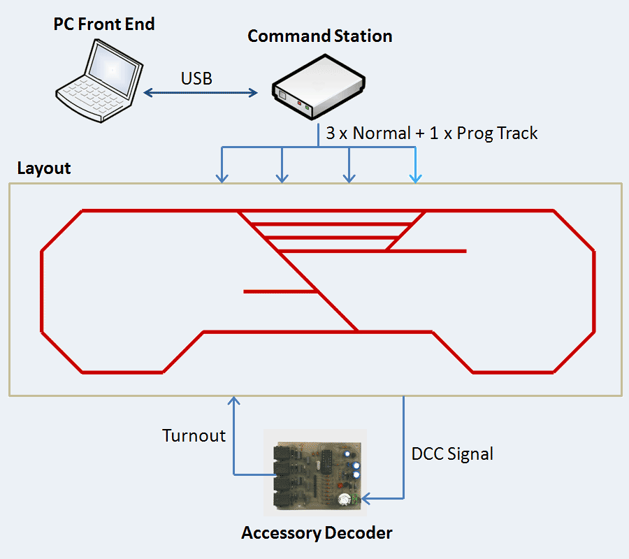
DCC Layout Block Diagram
A laptop running a program written in java provides all the controls for layout components like locos, turnouts, etc. It communicates with a PIC based command station over a USB port. The PIC based command station drives the layout. It has separate outputs for three normal rails and one programming rail used to program decoders in service mode. Besides driving the rails, the command station also drives accessory decoders.
Progress so far
The layout is ready and has been tested with a non-DCC loco. The PC front end works in standalone mode but has not beeninterfaced to the USB port.The software for the command station has been tested on the MPSIM simulator. The command station microcontroller is outputing idle packets. The command station output has not yet been connected to the driver which can drive the rails. I have a couple of DCC enabled locos ready to go.
Future Steps
Most of the system is still in individual pieces with not enough interfacing implemented to connect them together.
- The PC front end will be interfaced to the USB port
- The command station will have drivers to drive the rails
- At this point, I should be able to run one or more locos on the layout using DCC and the PC front end
- A more complex yard is planned with plenty of turnouts and may be even a turntable
- Accessory decoders for turnouts and a turntable are to be built. The front end already has capabilities to support this.
feedback
to  |