Stimulus Files for MPSIM using MS Excel
In my day...
In the old days when I dealt with micros I never used a simulator.
I used to think cross assemblers were cool. It took me a while to
look at MPSIM. Intially, it did not inspire much confidence as
a program that worked on the simulator often failed in real life.
With time, I realised it was all due to mistakes on my part - mistakes
in the .STI file, mistakes in interpreting the trace, etc. Now,
I do almost all my stuff on the simulator and test it well. It has
taken a lot of fun and excitement out of program development :-)
I use the DOS version of MPSIM. I have yet to get the hang of the
Windows version. For testing, creating a .STI file is half the
problem - the other half is wading through the trace file. This page
deals with the first half.
STI file format
The format of the STI file is described in the MPSIM doco. Briefly,
the first line is the header with the word STEP and the names of pins
for which signals will be injected. The subsequent lines have the step
number and the state of the pins to be injected. A comment can be placed
after a semicolon. MPSIM has commands to use the first column of figures
as the step no. or the time in us. You can also set the crystal
frequency. Here is a sample of a stimulus file.
	STEP	RB7
	100	0	; A comment
	933	1	;
	1766	1	;
	2599	0
Enter MS Excel
I use Excel to generate most of the input values. Here are two examples
- one for testing serial input at 1200 baud and the other generates a
DCC input for testing a DCC decoder. Once the spreadsheet is set up, I
copy the relevant columns into Notepad and save it as a .STI file.
STI file for Serial I/O
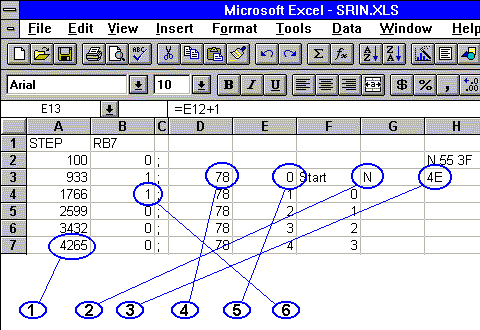
Here is a spreadsheet for an STI file for testing serial I/O. The serial
input is connected to the RB7 input on the PIC. No interface chip is
used - so the signal is inverted.

This was one of my initial attempts so it is not as automatic as I would
like. The top row of the spreadsheet has the header line. Going through
the various steps in creating the spreadsheet...
- The time in us. It starts at 100us and goes up in steps of 833us
which is the bit time for one bit at 1200 baud.
- The character to be sent out - in this case N.
- The hex representation of the character.
- The decimal representation which is repeated for each bit.
- The bit no. This goes from 0 to 10 i.e. 1 start bit, 8 data bits and
2 stop bits.
- The bit value. This is derived from the decimal representation and
the bit no.
A semicolon separates the derived data from the source. I usually
retain most of the original data as comments in the .STI file. To add
more characters, I just copy the 11 rows as many times I want
and type in the character I expect to send. Here
is a sample of the spreadsheet.
STI file for a DCC decoder
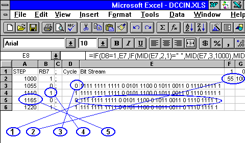
The DCC input is fed to the RB7 line on the PIC. The DCC signal is a
bitstream of 1s and 0s which is no surprise. The 1 is a high and a low
of 55 us and a 0 is a high and a low of 100 us.These times can vary a
little and the test should allow changing these. The DCC packet consists
of a preamble of 10 or more 1s, a 0, 8 bits of data and a 0 for each data
byte in the packet and an 8 bit error byte followed by a 1. Here is the
spreadsheet for the STI file.

- The bitstream to be reproduced. This consists of 12 bits of preamble
and the data and error bytes 5C, B3 and EF. Each alternate successive
row chops off the preceding bit and a space if there is one.
- The times for the 1s and 0s. These can be changed for different tests.
- The first and second half of a bit cycle. This is an alternate series
of 0s and 1s.
- The input value being injected. It is the same as the previous item.
- The time of the transition. This is the time of the previous
transition plus the bit time added. This time depends on the MSB of the
bitstream column,
Most columns have formulae to display nothing when it runs out of bits
to display. This makes it easy to mark and copy the relevant rows.
Here is a sample of the spreadsheet.


Updated on 1 Aug 96. Feedback to 


