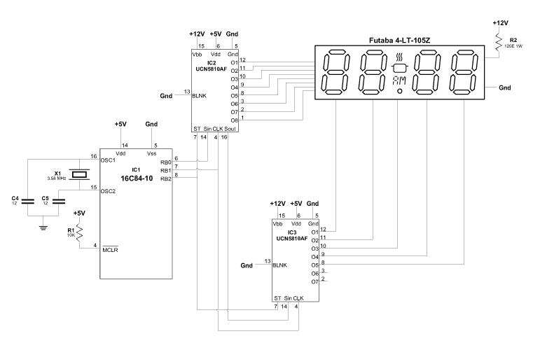
Vacuum fluorescent displays, known as VFDs(because both vaccuum and fluoroscent are hard to spell) are commonly used in VCRs and microwaves. They are relatively bright and have a low power consumption. Some older calculators used them before LCDs became popular. Having obtained a few Futaba VFDs from a surplus dealer, I went about trying to interface it to a PIC. A plea went out on the PIC list and was soon answered by Kalle Pihlajasaari with a few details on VFDs.
The VFD is a lot like a vacuum tube(remember them?) - in fact it is one except that the anode is coated with a phosphor which glows when hit by electrons. The filament requires about 40-120 mA at a few volts. Too high a voltage will make the filament glow red or even fail. Most displays have more than one filament wire in parallel. The filament is held at close to 0V. A high signal, usually 12V, on the grid and anode lights up the corresponding segments. The grid drives the digit and the anode drives the segments.
The VFD I used is a Futaba 4-LT-105Z. I bought it off a surplus dealer for AU$ 0.40 and could not find any data on it. The Futaba web site was no help and a search on the web turned up thousands of references to Futaba servos and little else. The VFD seems to have been made for an oven. It has 4 digits and a centre digit with a decimal point, an AM/PM symbol and symbols for a pot and steam. The leading digit has an AUTO symbol next to it. That is 5 digits and 7 segments - 8 if you count the AUTO symbol on the leftmost digit. The driver circuit would need 12 to 13 drivers.
I started off using two pins on the PIC for clock and data and shifting the data out serially. I planned on using a couple of shift registers to drive the VFD through ULN2003/ULN2803 chips. The drivers had pullup resistors. A high on the driver input pulled the output low and shut off the segment or digit. Although this configuration worked, the short duration when the bits are being shifted was enough to make some segments to glow weakly. It could be fixed by using latches or shift registers with built in latches. I, however, opted to use the Allegro VFD drivers which have shift registers and latches in the same package. Of the entire range, the 5810 was available at R.S. Electronics for about AU$9. This is the 10 bit version. The 32 bit version is also available in a 40 pin package. I used two 5810 chips - one for the eight segments and the other for the five digits. The datasheets for the 5810 are available on the Allegro web site.

The UCN5810AF is a VFD driver with 10 bit shift registers and output latches. Besides the ten outputs, there is a clock, serial in, strobe and blanking input and a serial out output. It also has a logic and load supply allowing easy conversion from the 5V logic level to the 12V required by the VFD. The 5810 is the 10 bit version. There are 12 bit(5811), 20 bit(5812) and 32 bit(5818) versions. The 12 bit version would have been ideal but was not easily available.
The two 5810s are cascaded by connecting the strobe and clock inputs together and connecting the serial out of the first chip to the serial in of the second. The blanking inputs are not used and are connected to ground. Three pins from the PIC drive the clock, serial in and strobe inputs.
The PIC uses a 3.58 MHz ceramic resonator. A periodic interrupt occurs at 130us. Every 4th interrupt a new digit is displayed. This should give a refresh rate of 2.5 ms for 5 digits or ~400 Hz. Each data bit is output on the port followed by a clock pulse. This shifts the data into the shift registers in the 5810. When all the bits have been output, the strobe output is pulsed. This latches the shift register outputs and makes the data appear on the chip outputs. The timing diagram below shows the signals on the data(RB0), clock(RB1) and the strobe(RB2) outputs. The main routine doesn't do much except show a series of numbers that are constantly updated. Have a look at the source and let me know what you think of it.
The three traces show the data, clock and strobe outputs. Using the 50us range, you can see that the clock pulses consists of two sets - the first one with 5 pulses for the digit information and the second with 8 pulses for the segment information. The first set of pulses shows it putting some information on the rightmost digit.
The timing diagrams are displayed using an interactive Java applet which uses the output of the MPSIM trace file. The contents of the trace file were filtered using the grep utility to give just the lines which refer to Port B. This file is used by the Java applet.
Noritake Co., Inc. has a good application note on VFDs.


