IR Receiver for Sony Remotes
The circuit is built to receive signals from a standard Sony remote control
and send the code bytes(2) received to an RS-232 port. It should not be
difficult to adapt this to any particular IR remote control. The Sony was
chosen because I happen to have a Sony VCR handy. An attempt to make it
work with an old Philips unit resulted in the discovery that this used a
different protocol for which I did not have any documentation.
Circuit Description

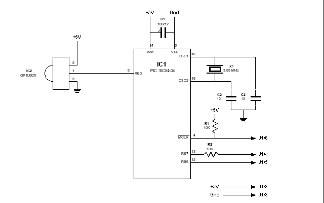
Circuit diagram in Postscript(28K)
This is probably the simplest PIC circuit I've ever put together. The Sharp IR
module GP1U52X does all the hard work - it senses the IR signal and sends out
the unmodulated signal. The most important thing is to ground the metal case of this
module. The most important thing is to ground the metal case of this module. The
most important thing is to... you get the picture. The PIC does the rest. It
then sends the received code on what passes for an RS 232 line to the PC. The
PC has a simple Visual Basic program which translates the received code
and displays the corresponding function in big letters. In other words, I
haven't found a useful application for this yet. Eventually, I plan to use it
to run my future model railroad.
The pin connections are for a 6 pin connector on the PCB and have the
following functions.
    Pin 1    Not used
    Pin 2    +5V
    Pin 3    Gnd
    Pin 4    RS-232 Rx
    Pin 5    RS-232 Tx
    Pin 6    External Reset
PIC Software
The PIC software consists of three files - ctrlir.asm
which contains the IR bitstream decoding logic,
ctrlcomm.asm which contains the logic for handling
RS-232 I/O and the corresponding include file ctrlcomm.h.
Some macros and values are defined in reg84.h.
These assembly file listings were created using a PIC assembly
to HTML converter. You can download the source as a
single zip file.
Like most of my programs, this one operates around having a periodic interrupt,
in this case one every 104us. This is used as a time base for everything
including the serial I/O. The serial I/O works at 1200 baud and this interrupt
rate gives 8 interrupts per bit.
The interrupt routine also reads the IR input. This gives a sampling rate of
one every 104us. For the Sony remote control, the header lasts about 2500us,
a mark lasts 1200us and a space 600us. Thus, the sampling rate is sufficient.
The ISR checks the state of the IR input and increments a register CurrTime,
for every interrupt where the state is unchanged. After a 0/1, a 1/0 and a 0/1
transition, it puts the number of ticks during the mark state and the space
state into two registers MarkTime and SpacTime. It also sets a
flag indicating that a bit is ready. The main routine then checks the values
and identifies the bit value. This is then shifted into a 16 bit word in
CodeByt1 and CodeByt2. When the end of transmission is detected by
sensing a very long space, the entire code is transmitted on the serial port by
the main routine. The actual transmission is done by the serial port ISR
which is called once every two interrupts or every 208us.
These routines are the first assembly listings I have published on the web. Most
of my assembly programming has been done in isolation. I would welcome any
comments/criticism on any aspect of the program.
Construction
I haven't designed a PCB for this circuit. It is trivial enough to be built on
a piece of veroboard. Have I mentioned that the case of the Sharp module must
be grounded?
Front-end Software
This is a rudimentary Visual Basic program which gets the two bytes for each code
from the PIC on the RS-232 port
and displays them as hex digits. If the function exists in the lookup
table held in the program then the function is displayed in large characters.
You can download the source and executable for this program.


Updated on 6 Jan 98. Feedback to 

