The first accessory decoder I am building is for controlling turnouts. This accessory decoder controls four turnouts. The turnout motors are Peco and are twin coil solenoid types. These need to be briefly activated to switch the turnout. Using DCC to control layout accessories simplifies the wiring considerably. The previous design I had for turnout motors controllers needed several connections - 5V, 16V, Gnd, one control line for each motor. With the DCC accessory decoder, all I need is two connections from the nearest rail feed.
The turnout decoder is PIC 16F628 based. Some of the features listed here will be implemented right away while others are just wishful thinking.
A voltage doubler turns the DCC signal which is approximately 12V to about 23V. This higher voltage is necessary to drive the turnout motor with a capacitive discharge. The current requirements are that of the capacitor charger(100mA) and the PIC. The PIC 16C84 running at 10MHz is supplied 5V by a 7805. A voltage divider running directly off the DCC line provides the PIC with the DCC input. The internal diode on the PIC clamps the voltage. The PIC outputs drive the two coils in each turnout motor. The eight outputs go to BD679 Darlington transistors. These transistors are activated to discharge the capacitor through the turnout coil. The diode on the collector protects the transistor from voltage peaks. The capacitor is charged using a constant current source built around a PNP low power transistor and an LED as a voltage reference.
Using a constant current charge source speeds up the charging of the capacitor while keeping an upper limit on the charge surge current. Turnout motors that use a solenoid type mechanism like the Peco ones, need a large surge of current for a short time. A capacitor discharge circuit is ideal for providing this. The capacitor usually has a resistor in series to limit the charge current. This current may also flow through the motor coil in case of a malfunction in the driver transistor. For this reason and also to limit the initial surge, the series resistor has to be kept relatively high. This, however, will result in a longer charge time and reduce the cycle time. The surge current demands place a heavy load on the power supply with a large number of turnouts used.
A constant current supply gets around all these problems. The current level can be kept fairly low while still allowing a low cycle time. If the current rate is kept at 100mA for a +24V supply, a 1000uF capacitor should take about 0.25 seconds. For the same value of max. current you would need a 240 ohm resistor in series. This would take about 1.2 seconds. For the capacitor to charge in the same time i.e. 0.25 seconds, it would take a 50 ohm resistor with a surge current of 500mA. With the lower current requirement for a constant current charge, the max. drain on the DCC command station will be reduced. Each turnout decoder controls the turnouts so that only one is fired every 0.25 seconds. I intend to use one of the outputs from the command station for accessory decoders. Assuming the current rating of that output to be 1A, 10 turnout decoders or 40 turnout motors can be powered. This is assuming the worst case of all of them receive commands to actuate at the same time.
The RTCC is not preloaded and interrupts when it overflows. With a 10MHz crystal, the interrupt occurs once every 102.4us. The timer ISR stores the 'overflow' in two more bytes. The first byte will overflow once every 256 * 102.4 = 26.2ms. The second byte will overflow once every 256 * 26.2 = 6.71 secs. The DCC signal is routed to RB5 which is configured to interrupt whenever the DCC signal changes polarity. This is timed and the bit period determined. This is then decoded into bit streams and then to DCC commands.
The commands are used to update the desired state of the coils stored in a nibble. The current state of the coils is stored in another nibble. The coil activation routine has three states - idle, activating a coil and charging up the capacitor. In its idle state, it looks for differences between the current state and the desired state. If it finds a difference the most significant differing bit is extracted and the coil corresponding to it is activated. Each motor consists of two coils and a 0 implies one coil being activated and 1 implies the second one. Once the activation times out, the drive to the coil is deactivated. The routine moves to the capacitor recharge state. Once this state times out, the routine looks for more differing bits. If there it finds one it does the whole thing again - otherwise it goes back to idle state and keeps polling for differences.
The process above ensures that only one coil is activated at a time as the capacitor may not have the charge to activate two coils at once. It also ensures that the capacitor has had sufficient time to charge before it is used to activate a coil.
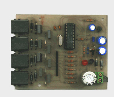
As this was the second component I was designing and building, the first being the command station, I decided to design a proper PCB for this circuit. The PCB layout and the legend overlay are available as PDF files. I made the PCBs myself but that's another story.


